Efficient optimization of laminate type and layup orientation for composites

»SIMUTENCE engineering and simulation methods enable an efficient design of composite parts. But how to efficiently determine laminate layups including the stacking type and ply orientations?
We’ll answer this question below.«

Introduction

Continuously fiber-reinforced polymers (CoFRP) offer high weight-specific material properties, making them well suited for lightweight applications. To achieve a high level of lightweighting, optimization strategies need to be integrated into the design workflow. However, due to the anisotropic behavior of composite materials, common optimization approaches for engineering challenges, like topology or shape optimization, are not perfectly suited. Therefore, composite-specific optimization strategies are required to fully leverage their potentials for lightweighting.

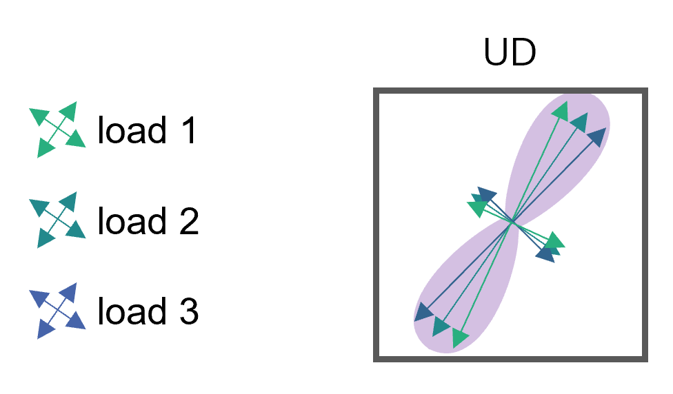
CoFRP offer for optimization tasks two major degrees of freedom: layup orientation and layup type. A common approach to optimize material orientation is computer-aided internal optimization (CAIO) [1]. This approach aims for an element-wise minimization of shear stresses, leading to a laminate orientation well-suited for unidirectional (UD) layups. The material is therefore oriented locally in direction of the maximum principal stress. This approach is well-suited to optimize the material orientation for parts loaded with a single load case with UD layups only. However, other layup types and multiple loads or even load cases cannot be accounted for. However, both focus on the optimization for load cases with a single load only and do not take into account the orientation of the laminate for optimization.

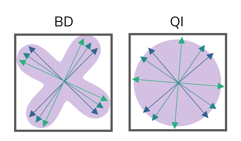
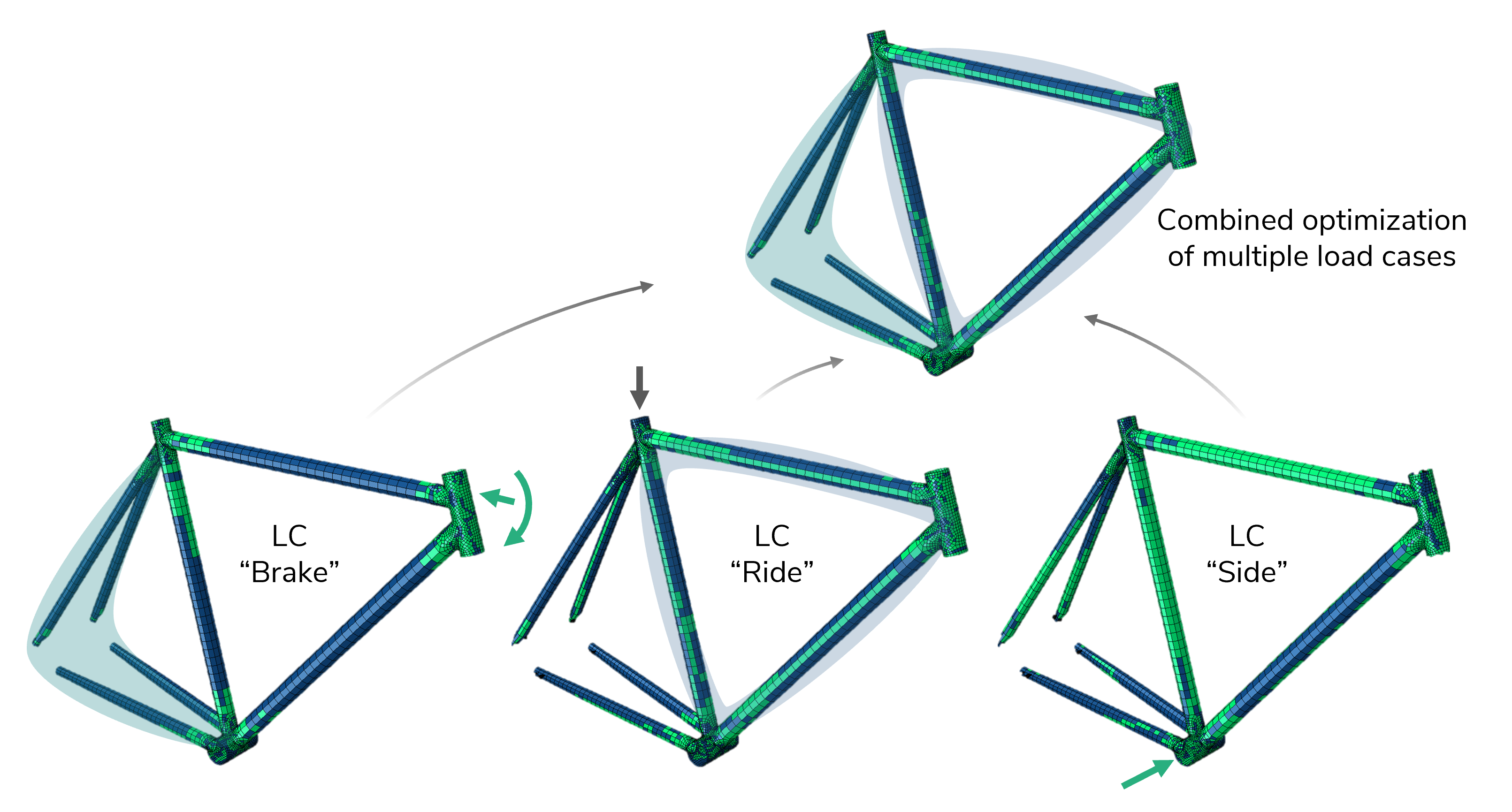
The challenges for the optimization of CoFRP components are to account for multiple loads in multiple load cases, as well as to optimize both the layup type and layup orientation. Incorporating the layup type as a degree of freedom into the optimization allows for better exploitation of the lightweight potential of CoFRP components. Therefore, a combined optimization for the layup type and layup orientation is key.

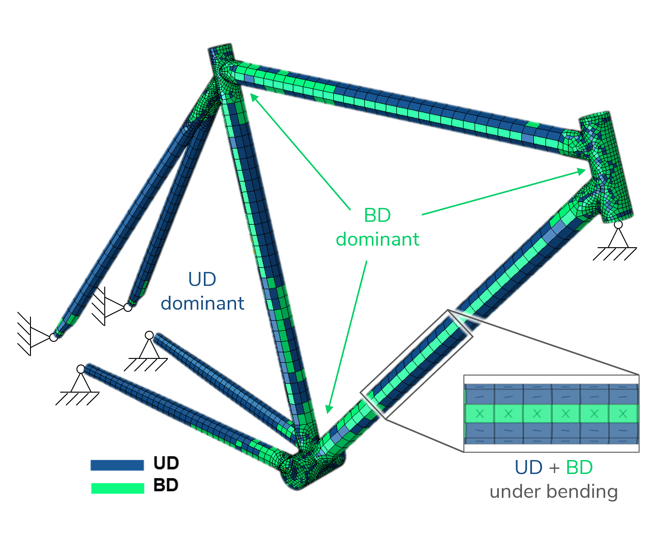
An anisotropy analysis, which has originally been presented by Zink et al. [3], is facing this challenge. The result of this approach is a laminate design best-suited for manufacturing strategies like automated tape placement (ATP).

Recently, we have adopted and further developed in cooperation with KIT-FAST the anisotropy analysis. Now, SimuOpt, a tool that is capable to efficiently optimize layup orientation and layup types for CoFRP components exposed to multiple loads in multiple load cases, is available.

Methodology

The workflow of the anisotropy analysis consists of three major steps:

  1. Calculation of local stresses
  2. Element-wise evaluation of an optimality criterion (OC)
  3. Assignment of the layup orientation.

The computation of the local stresses is performed for each load case individually. Subsequently, a combined evaluation of the OC is performed to find the best layup type and layup orientation in each element. The layup types considered are unidirectional (UD), bi-directional (BD), and quasi-isotropic (QI). In an iterative procedure, first, all elements are considered to be QI elements, while for the subsequent iterations individual layup orientations and layup types are assigned to each element. The optimization procedure is terminated after a user-defined iteration limit is reached. This iterative procedure is required since the analysis is based on the local stresses, which are significantly influenced by fiber orientations being optimized in each iteration.

Each iteration consists of three substeps. First, the preferred layup orientations are determined. Here, QI does not require an orientation due to isotropy. Subsequently, a reserve factor is assigned to each layup type, according to the existing stress states in the element. The last step is a comparison of the layup types and the selection of the best-suited layup type.

For more details, please refer to our publications [4-6].

Exemplary evaluation of three different load sets, each consisting of three individual loads, for a single element and comparison with the corresponding material stiffness. The load sets show results for a UD (A), BD (B), and QI (C) layup [4].

Application example

The capability of the anisotropy analysis is demonstrated using a bike frame as an application example. The layup orientation and layup type are optimized for the bike frame considering three different load cases.

Load cases considered for the anisotropy analysis of the bike frame [4].

Generally, the anisotropy analysis is not limited to a specific number of load cases to be used. Due to its fundamental approach, the anisotropy analysis can only find BD and UD areas for a single load case. In contrast, a too large number of significantly different load cases usually results in a QI-dominated layup.

The anisotropy analysis of the bike frame reveals areas with dominant UD material, especially in the rear truss tubes, since tensile stresses are predominant. However, areas with higher bending loads (mainframe and joints) are BD-dominated.

Furthermore, it is observed that the optimization procedure converged already after a small number of iterations. This makes the developed method highly suitable also for the optimization of large components.

Results of the combined optimization for all load cases and detailed view of the result, showing orientation and layup type [4].

Conclusion

Continuously fiber-reinforced polymers (CoFRP) offer several different parameters to be optimized for specific applications. Especially the layup type and the layup orientation have a significant influence on the structural performance. These parameters can be optimized using a so-called anisotropy analysis.

The anisotropy analysis is highly efficient also for large components since only a small number of finite element calculations are required. Additionally, multiple load cases including several loads within one load case can be considered in a single run. This allows achieving a synthesis of the structural requirements from the different load cases within a single optimization run.

Therefore, the anisotropy analysis serves as a perfect add-on to the virtual process chain, since it allows to efficiently optimize CoFRP designs and to fully exploit the lightweight potential.

Any questions?

Do not hesitate to get in contact with us if you have any questions or if you are interested in a collaboration. We are pleased if you leave us a message!

References

  1. R. Kriechbaum, CAIO (Computer Aided Internal Optimization): A powerful method to optimize fiber arrangement in composite materials, First European Conference on Smart Structures and Materials, SPIE, 1992.
  2. N. Zehnder and P. Ermanni: Optimizing the shape and placement of patches of reinforcement fibers, Composite Structures, vol. 77, no. 1, pp. 1–9, 2007.
  3. C. Zink and P. Middendorf: Automated design approach and potential assessment of composite structures: fast analytical engineering tool for multiple load cases, Proceedings of ECCM17 Munich, 2016.
  4. C. Zimmerling, B. Fengler, H. Wen, Z. Fan, L. Kärger: Rapid Determination of Suitable Reinforcement Type in Continuous-Fibre-Reinforced Composites For Multiple Load Cases, Virtual ICCS23, Porto, 2020.
  5. B. Fengler, C. Zimmerling, L. Kärger: Rapid determination of suitable reinforcement in continuous-fiber-reinforced composites for multiple load cases, Proceedings of SAMPE Europe Conference 2021 Baden/Zürich, 2021.
  6. C. Zimmerling, B. Fengler, C. Krauß, L. Kärger: Optimisation of Layup Type and Fibre Orientation in Continuous-Fibre Reinforced Components via Anisotropy Analysis, Composites Structures, 2021 (submitted).